|
|
||||||||||||||
|
||||||||||||||
|
||||||||||||||
bootblock.s |
||||||||||||||
| Skip to line: 2025 - 2050 - 2075 - 2100 - 2125 - 2150 - 2175 - 2206 | ||||||||||||||
| If you have a comment for bootblock.s, please click here. | ||||||||||||||
|
|
||||||||||||||
|
|
||||||||||||||
|
||||||||||||||
|
||||||||||||||
bootblock.s |
||||||||||||||
| Skip to line: 2025 - 2050 - 2075 - 2100 - 2125 - 2150 - 2175 - 2206 | ||||||||||||||
| If you have a comment for bootblock.s, please click here. | ||||||||||||||
|
|
||||||||||||||
|
2000 ! Bootblock
1.4 - Minix boot block.
Author: Kees J. Bot
2001 ! 21 Dec 1991 2002 ! 2003 ! When the PC is powered on, it will try to read the first sector of floppy 2004 ! disk 0 at address 0x7C00. If this fails due to the absence of flexible 2005 ! magnetic media, it will read the master boot record from the first sector 2006 ! of the hard disk. This sector not only contains executable code, but also 2007 ! the partition table of the hard disk. When executed, it will select the 2008 ! active partition and load the first sector of that at address 0x7C00. 2009 ! This file contains the code that is eventually read from either the floppy 2010 ! disk, or the hard disk partition. It is just smart enough to load the 2011 ! secondary boot code from the boot device into memory at address 0x10000 and 2012 ! execute that. The disk addresses for this secondary boot code are patched 2013 ! into this code by installboot as 24-bit sector numbers and 8-bit sector 2014 ! counts above enddata upwards. The secondary boot code is in turn smart 2015 ! enough to load the different parts of the Minix kernel into memory and 2016 ! execute them to finally get Minix started. |
|
|
|
It's also important to know that dl contains the drive that
was booted (in other words, the drive from which this code originated).
This is 0x00 or 0x01 for the first or second floppy drives or 0x80, 0x81,
0x82, or 0x83 for the first through fourth hard drives.
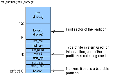
If this code originated from a hard drive and the master boot code loaded this code, then the partition table entry that corresponds to the booted partition is passed in es:si. | ||
|
2018
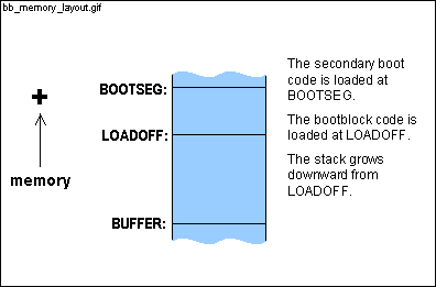
2019 LOADOFF = 0x7C00 ! 0x0000:LOADOFF is where this code is loaded 2020 BOOTSEG = 0x1000 ! Secondary boot code segment. 2021 BOOTOFF = 0x0030 ! Offset into secondary boot above header |
|
|
| ||
|
|
| ||
|
2024
! table
2025 |
|
|
|
|
|
|
|
|
|
This is fairly common practice in assembler. Several values are
pushed on the stack (lines 2043, 2044, and 2046) and then the stack pointer,
sp ,
is saved in bp (mov bp, sp - line 2047). If 2 byte
values are pushed on the stack, then the last 2 bytes are accessed by 0(bp) ,
the next-to-last 2 bytes are accessed by 2(bp) , and so on (see
line 2095).
While these 3 variables take up 8 bytes, only 6 bytes are pushed onto the stack. lowsec (lines 2043 and 2044) and device (line 2046) are pushed, but what about secpcyl ? When a value is finally stored in secpcyl (line 2110), the first 2 bytes of the bootblock code are overwritten - the first xor ax, ax instruction (line 2036) is overwritten. This doesn't matter since the code never jumps back to the beginning. This saves not only the 2 bytes needed for the variable but also the memory required for a push instruction. | ||
|
|
|
|
|
The first instruction zeroes the ax register (any number xor'ed
with itself is zero). This is a pretty common practice. The
instruction
mov ax, #0 is slower and is 3 bytes compared with xor's 2 bytes. One thing that initially confuses people with assembler is the order of the operands. The syntax of the mov instruction is: mov destination, source This seems a little strange to me but most assemblers use this syntax. | ||
|
|
|
|
|
|
|
Whenever a value is moved to the stack register (ss)
or the stack pointer (sp), the interrupts must be disabled first.
The stack holds the address to which an interrupt returns after its completion.
If the ss and
sp registers are in flux and an interrupt
occurs, it's impossible to predict where the code will return.
The interrupts are disabled with the cli (clear interrupts) instruction and reenabled with the sti (set interrupts) instruction. What's the pound (#) sign all about? The pound sign indicates that the value of LOADOFF (0x7C00 - see line 2019) is moved to the register rather than the contents of the memory location LOADOFF. | ||
|
2042
2043 push ax 2044 push ax ! Push a zero lowsec(bp) 2045 2046 push dx ! Boot device in dl will be device(bp) |
|
|
| This is a little technical, but I believe the idea is that an immediate instruction is one byte larger than a special address mode instruction (ss:disp[bp]). For example, the instruction on line 2095 is one byte smaller than it would have been if 2 bytes had been set aside (using .data2) for lowsec and the mov es, LOADOFF+lowsec instruction were used. Since the bootblock code and sector addresses (see lines 2204-2206) must fit in a single block (1 block = 2 sectors = 2 * 512 bytes = 1024 bytes), space needs to be conserved. Since a stack doesn't take up any hard drive space, hard drive space is saved by not allocating space within the code (using .data1 or .data2). | ||
|
2048
2049 push es 2050 push si ! es:si = partition table entry if hard disk 2051 |
| di now points to sectors (line 2200). | ||
| 2053 |
|
|
|
|
| testb sets the sign flag if the value in dl is negative. If dl is not negative, jge jumps to floppy. When is the value negative? In two's complement notation, if the rightmost bit is a 1 then the value is negative. So for a one byte value, anything greater than 0x7F (=0111111) is negative. Remember that 0x00 and 0x01 correspond to the first and second floppy drives and 0x80, 0x81, 0x82, and 0x83 correspond to hard drives 1-4. | ||
|
2056
2057 winchester: 2058 2059 ! Get the offset of the first sector of the boot partition from the partition 2060 ! table. The table is found at es:si, the lowsec parameter at offset LOWSEC. 2061 |
|
|
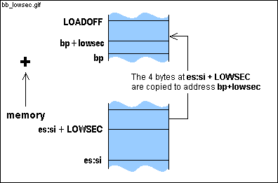 An instruction prepended by eseg uses es (instead of ds) as the segment register. The les instruction loads the register specified by the first operand (in this case ax) with an offset address and es with a segment register. The value at es:LOWSEC(si) is loaded in ax and the value at es:LOWSEC+2(si) is loaded in es. The eseg prefix is needed since es:LOWSEC(si), not ds:LOWSEC(si), is the memory address that holds the lowest sector (see comment for line 2017). Note that the es and ax registers are overwritten by the eseg les ax, LOWSEC(si) instruction. For this reason, the es and ax registers were pushed onto the stack on lines 2049-2050. | ||
|
2066
2067 ! Get the drive parameters, the number of sectors is bluntly written into the 2068 ! floppy disk sectors/track array. 2069 2070 movb ah, #0x08 ! Code for drive parameters |
|
|
| int 0x13, ah=0x08 returns the device geometry of the drive specified by dl. dl will be 0x80 for the first drive, 0x81 for the second, 0x82 for the third and 0x83 for the fourth. int 0x13, ah=0x08 returns the maximum sector number in bits 0-6 of cl and the maximum head number in dh. Adding to the confusion, the value that int 0x13, ah=0x08 returns for the maximum head number has a 0-origin. This means that if int 0x13, ah=0x08 returns a 15 for the maximum head number, there are actually 16 heads; dh is incremented on line 2074 to move to a 1-origin. | ||
|
2072
andb cl, #0x3F !
cl = max sector number (1-origin)
2073 movb (di), cl ! Number of sectors per track 2074 incb dh ! dh = 1 + max head number (0-origin) 2075 jmp loadboot 2076 |
|
|
|
|
|
|
|
|
|
|
| An attempt to read the 18th sector on the first track of the floppy is first made. If that attempt fails, the drive specified by dl (either 0x00 or 0x01) is not a functioning 1.44M floppy drive. An attempt to read the 15th sector on the first track is next made. If that fails, the drive specified by dl is not a functioning 1.2M floppy drive. An attempt to read the 9th sector is the final attempt (for 720K/360K floppy drives). | ||
| 2082 |
|
|
| di points to sectors (see lines 2052 and 2200). | ||
| 2084 |
|
|
| int 0x13, ah=0x00 resets the drive specified by dl. | ||
|
2086
int 0x13
2087
2088 movb cl, (di) ! cl = number of last sector on track 2089 2090 cmpb cl, #9 ! No need to do the last 720K/360K test 2091 je success 2092 2093 ! Try to read the last sector on track 0 2094 2095 mov es, lowsec(bp) ! es = vector segment (lowsec = 0) |
| The memory region beginning at address BUFFER is not being used for anything now, so this region can be used as scratch area and hard drive sectors can be copied there to test out the floppy drives. | ||
|
2097
mov ax, #0x0201 ! Read
sector, #sectors = 1
2098 xorb ch, ch ! Track 0, last sector 2099 xorb dh, dh ! Drive dl, head 0 |
|
|
| int 0x13, ah=0x02 copies sectors from a hard drive or floppy to memory. al specifies the number of sectors to copy, bits 0-5 of cl specify the sector number, dh specifies the head number and ch specifies the low 8 bits of the cylinder number and bits 6-7 of cl specify the high bits of the cylinder number. es:bx specifies where in memory to load the sectors. If the int 0x13, ah=0x02 call fails, the carry (C) flag is set. If the carry flag is set, the jc instruction (line 2101) jumps to memory address next (line 2083). | ||
|
2101
jc next
! Error, try the next floppy type
2102 |
|
|
| A floppy is a single disk with 2 heads, one for each side. | ||
| 2104 |
|
|
|
Lines 2105-2153 are the heart of bootblock. The sectors listed
at memory address addresses (line 2204) are loaded; these sectors
make up the secondary boot. The sector numbers were patched at addresses
by the installboot
utility program.
Grinding through this code isn't fun. Everything until line 2141 sets things up for the int 0x13 bios call. | ||
|
2106 ! Load the secondary boot code from the boot device
2107 2108 movb al, (di) ! al = (di) = sectors per track |
|
|
| mulb multiplies al by the operand (in this case dh). The result is placed in ax. | ||
|
2110
mov secpcyl(bp), ax ! Sectors
per cylinder = heads * sectors
2111 2112 mov ax, #BOOTSEG ! Segment to load secondary boot code into 2113 mov es, ax 2114 xor bx, bx ! Load first sector at es:bx = BOOTSEG:0x0000 2115 mov si, #LOADOFF+addresses ! Start of the boot code addresses 2116 load: |
|
|
|
|
|
|
| The installboot utility patches in 2 values for each 4 byte entry at addresses. It uses the 1st byte of the entry for the count and the 2nd, 3rd and 4th bytes of the entry for the sector number (actually, it's the offset of the sector within the partition - see comments for 2120-2121). The best way to describe the count is with an example. If the secondary boot code is found at sectors 500, 501, 502, 509, and 510, there would be two entries at addresses - the first entry would be count=3, sector number=500 and the second entry would be count=2, sector number=509. | ||
| The value patched at addresses is the offset of the sector within the partition, not the absolute sector number. The int 0x13, ah=0x02 bios call needs the absolute sector number so lowsec is added to the offset (lowsec is the first sector of the partition). | ||
|
2122
div secpcyl(bp)
! ax = cylinder, dx = sector within cylinder
2123 xchg ax, dx ! ax = sector within cylinder, dx = cylinder 2124 movb ch, dl ! ch = low 8 bits of cylinder |
|
|
| The divb instruction divides ax by the operand (in our example (di) - di points to the memory address that holds the number of sectors per track) and puts the quotient into al and the remainder into ah. | ||
|
2126
xorb dl, dl
! About to shift bits 8-9 of cylinder into dl
2127 shr dx, #1 2128 shr dx, #1 ! dl[6..7] = high cylinder 2129 orb dl, ah ! dl[0..5] = sector (0-origin) 2130 movb cl, dl ! cl[0..5] = sector, cl[6..7] = high cyl 2131 incb cl ! cl[0..5] = sector (1-origin) 2132 movb dh, al ! dh = al = head 2133 movb dl, device(bp) ! dl = device to read |
|
|
|
|
|
|
|
|
|
|
|
The int 0x13, ah=0x02 bios call can only read sectors from
a single track at a time. Lines 2134-2138 calculate the maximum numbers
of sectors that can be read without crossing a track boundary.
cmp is a subtraction that only affects the flag register. jbe (line 2137) jumps if the first operand in cmp is below or equal to the second operand. | ||
|
2139 read: push ax
! Save al = sectors to read
2140 movb ah, #2 ! Code for disk read (all registers in use now!) |
|
|
| int 0x13, ah=0x02 copies sectors from a hard drive or floppy to memory. al specifies the number of sectors to copy, bits 0-5 of cl specify the sector number, dh specifies the head number and ch specifies the low 8 bits of the cylinder number and bits 6-7 of cl specify the high bits of the cylinder number. es:bx specifies the memory address where the sectors are loaded. If the int 0x13, ah=0x02 call fails, the carry (C) flag is set and an error code is placed in ah. If the carry flag is set, the jc instruction jumps to memory address error (line 2170). | ||
|
2142
pop cx
! Restore al in cl
2143 jc error ! Jump on disk read error 2144 movb al, cl ! Restore al = sectors read |
|
|
|
|
|
int 0x13, ah=0x02 writes the sectors to es:bx.
What's done here is somewhat tricky. If 1 is added to bh, it is equivalent to adding 256 to bx. If 2 is added to bh, it is equivalent to adding 512 to bx (remember that 1 sector = 512 bytes). | ||
|
|
|
|
|
|
| Lines 2147-2149 modify the count and sector number in case the consecutive sectors crossed a track boundary and all the sectors could not be read. | ||
| 2150 jnz load ! Not all sectors have been read |
|
|
| si points to the current entry. To move to the next entry, 4 is added to si (each entry is 4 bytes). | ||
|
2152
cmpb ah, (si)
! Done when no sectors to read
2153 jnz load ! Read next chunk of secondary boot code 2154 |
|
|
| When the entire secondary boot has been loaded, the code falls through to done . | ||
|
2156
2157 ! Call secondary boot, assuming a long a.out header (48 bytes). The a.out 2158 ! header is usually short (32 bytes), but secondary boot has two entry points: 2159 ! One at offset 0 for the long, and one at offset 16 for the short header. |
|
|
|
|
|
|
|
|
|
|
|
Click here
to look at boothead.s.
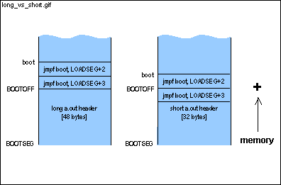
If the secondary boot has either a short header or a long header, the instruction at BOOTSEG:BOOTOFF jumps to the boot address. These are the same parameters that were passed to the bootstrap (this code). Keep three things in mind: 1) BOOTSEG (defined in this file) and LOADSEG (defined in boothead.s) are both defined as 0x1000. 2) Adding 2 to the segment register adds 32 to the address formed by the segment:offset registers and adding 3 to the segment adds 48 to the address formed by the segment:offset registers. 3) boot is the offset from the end of the header. | ||
|
2165
pop si
! Restore es:si = partition table entry
2166 pop es ! dl is still loaded 2167 jmpf BOOTOFF, BOOTSEG ! jmp to sec. boot (skipping header). 2168 2169 ! Read error: print message, hang forever |
|
|
|
If something goes wrong, the code ends up here. After a failed
int0x13, ah=0x02 bios call, ah holds the error code.
It helps to look at an ascii chart before trying to understand the following code. The ascii string at errno (line 2196) is modified. The *second* digit is first incremented to reflect (in ascii representation) the value in the left-most 4 bits of ah. If the right-most 4 bits of ah are nonzero, the code loops back to prnum and increments the *first* digit to reflect (in ascii representation) the value in the right-most 4 bits of ah . | ||
|
2171
mov si, #LOADOFF+errno+1
2172 prnum: movb al, ah ! Error number in ah 2173 andb al, #0x0F ! Low 4 bits 2174 cmpb al, #10 ! A-F? 2175 jb digit ! 0-9! 2176 addb al, #7 ! 'A' - ':' 2177 digit: addb (si), al ! Modify '0' in string 2178 dec si 2179 movb cl, #4 ! Next 4 bits 2180 shrb ah, cl 2181 jnz prnum ! Again if digit > 0 2182 |
| Note that the strings on lines 2195-2196 occupy consecutive memory addresses and end at errend. One character at a time is printed until errend is reached. | ||
|
2184 print: lodsb
! al = *si++ is char to be printed
2185 movb ah, #0x0E ! Print character in teletype mode 2186 mov bx, #0x0001 ! Page 0, foreground color |
|
|
| int 0x10, ah=0x10 prints the character in al to the current cursor position and advances the cursor. bh holds the active page and bl holds the foreground color. | ||
|
|
| Note that after reaching errend, the code falls through to hang. | ||
|
2190
2191 ! Hang forever waiting for CTRL-ALT-DEL 2192 hang: jmp hang 2193 2194 .data 2195 rderr: .ascii "Read error " 2196 errno: .ascii "00 " 2197 errend: 2198 2199 ! Floppy disk sectors per track for the 1.44M, 1.2M and 360K/720K types: 2200 sectors: 2201 .data1 18, 15, 9 2202 2203 .align 2 |
|
|
|
|
|
|
|
The installboot utility patches
(count, sector address) pairs here. Look at line 2105 and lines 2117-2119
for a detailed explanation.
This code and the the secondary boot addresses have to fit into a single block (hence the name "boot block"). 1 block = 2 sectors = 2 * 512 bytes = 1024 bytes. If there is space for a 66K secondary boot when the secondary boot is fragmented (meaning that no 2 sectors are consecutive) then that means that there is space for (66K * 2 sectors/K=) 132 (count, sector address) entries. Each entry takes up 4 bytes so the total space taken up by the entries is 528 bytes. So the actual code (everything but the entries) takes up the remaining (1024-528=) 496 bytes. | ||
|
|
| end of file |